


|
||||||||||||||||||||||||||||||||||||||||||
|
This is the third Stirling engine that I have built. It is made after the plans from Darryl Boyd on http://www.boydhouse.com/stirling/index.html . Go watch the plans plus very many pictures of models that other people have built.
|
|
|
|
|
|
|
|
|
;)
;)
;)
;)
;)
;)
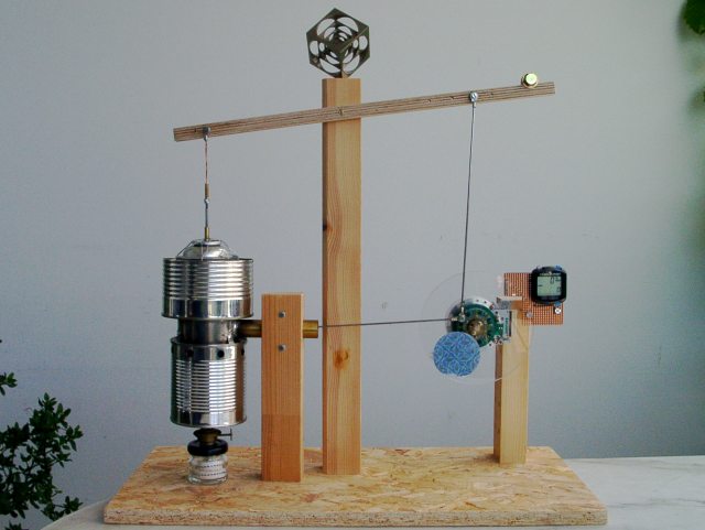
At a later time I may replace the 'heavy' tomato can as displacer piston with a lighter and better fitting one, maybe from balsa wood or an aluminum can, to speed the machine up a little.
For most of the parts I have used recycled material. The walking beam, the main engine and the flywheel support are made from an old wooden book shelf.
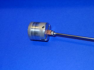
 Power Piston
Next you can see the power piston, that a friend has made
for me on his lathe.
Photo 8: I
used my small Unimat lathe to make a good fit between the power
piston and the power cylinder. I made a large excenter
disc to move the piston often
with some polishing powder and oil between the surfaces.
|
|
|
|
;)
;)
;)
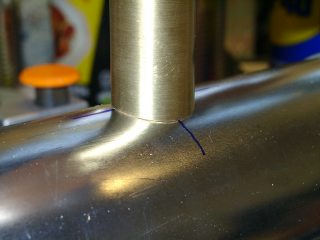
Power and Displacer Cylinders
Photo 10 shows the hand filed fit between the two, for which the software "Winmiter" was a great help. Pic 11 shows my drillstand being used as fixture for soldering.
Photo 16: the top of the display cylinder was not soldered to the body, but fixed with some wire (see photo 01). It is airtight due to a rubber gasket in the top rim.
|
|
|
|
|
|
|
|
|
|
;)
;)
;)
;)
;)
;)
;)
;)
Flywheel and rods
For the bearing of the flywheel I used the head of a dumped video recorder, which shows nice details of the synchronous head motor. The rods are made from bicycle spokes, connected with round electrical terminals crimped then soldered to the rods (idea from Rex James, Australia).
Click on the thumbnails to enlarge the photos:
|
|
|
|
|
;)
;)
;)
;)
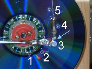
I made some experiments with the length of way that
the power piston travels (rod positions 1 to 5 in pic
18). Too short is obviously not
good, but too long as well. To study this, I added
the blue mark on the slotted hole of the horizontal
rod (arrow). Flashlight photos unveil what happens.
I noticed the piston being
sucked back in (to the left) while the piston was still
being moved to the right from the flywheel when the
travel distance was too large.
For these
experiments I used a 100W light bulb as a heat
source: my spiritus flame was not constant enough
to tell the differences of my adjustments.
After
the tests with the CD stack I used a plexiglass disk
as a flywheel, enhanced with a reflective foil (pics
01 and 02).
Tachometer
As something special I added the computer from my bicycle, which has a cadence sensor. I just added a reed contact and a small magnet to the flywheel, and voila, the readout is directly in rpm (revolutions per minute). See photo 21. A bike computer without cadence sensor can be used with less accuracy: set the wheel circumference to 1666 mm: the speed reading 6 km/h means 60 rpm.
Performance
The maximum safe engine speed was around 150 rpm. It was a bit higher once, but the soldering of the fire box disintegrated due to too much heat. Next time I would use a better solder (braze) for the fire box and the power cylinder.
The machine took a while to be finished. Collecting the material was quite time-consuming. The construction phase was finished in August 2006.
As a summary, it was not easy to make the machine run well. Friction must be minimised everywhere. But it was a lot of fun. Thanks, Darryl, for the plan and your great website.
Dimensions
Power piston diameter: 18 mm
Power
piston travel length: 42 mmm
distance crank point
on fly wheel to center: 21 mm
left arm of walking
beam: 147 mm
right arm of walking beam: 145 mm

Copyright(c) 2006 by uh-lab.de