


|
|||||||||||||||||||||||||||||||||||||||||||||||||||||||||||||||||
|
|
In the meantime I got myself a small lathe and a mill to build more serious machines. Again on the website of Koichi Hirata, the Japanese Stirling professional, I found the plans for a simple Stirling machine which needs some machining, the LSE-01. It seemed simple enough for me to start learning how to operate my newly acquired lathe and mill.
|
||||||||||||||||||||||||||||||||||||||||||||||||||||||||||||||||
|
|
|
|
|
;)
;)
;)
;)
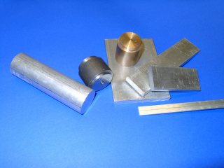
 The parts of the machine
The next list of pictures show some of the parts after they have been machined.
Click on the pics to enlarge.
|
|
|
|
|
|
|
|
|
|
;)
;)
;)
;)
;)
;)
;)
;)
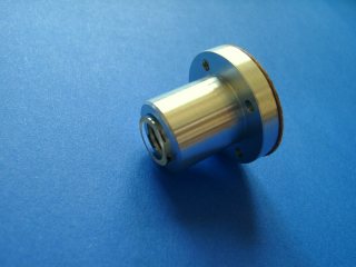
The glass cylinders are already glued with "Sikaflex-292" silicone glue into the cylinder cover. One must be very careful to keep the glass surfaces ultra-clean. Even a fingerprint on the piston makes enough friction that it is hard to move inside the cylinder.
I have changed the flywheel quite a bit compared to the plan, where it was only a flat disk.
Assembly of the machine
It was a good feeling to put all these parts together.
Click on the pics to enlarge.
|
|
|
|
|
|
|
|
|
|
|
|
|
|
|
|
|
|
;)
;)
;)
;)
;)
;)
;)
;)
;)
;)
Again a small change in the plans: for the connecting rods I used bush bearings out of brass (pic 22) instead of the 2 mm screws rotating directly inside the aluminum rods. I found that this had less friction and less radial clearance. These bushings are so tiny to hold that I made a simple vice for it (pic 23).
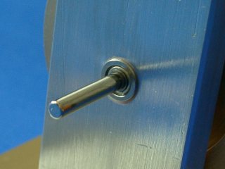
The slide gauge in pic 27 shows the clearance above the hot piston - 2 mm only between the piston top and the 'roof' of the heater!
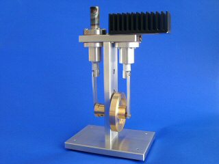
The machine can only run with a sufficient temperature difference between the hot and cold cylinder. To maintain this I added a heat sink: for the prototype I used what I found in my cabinet: an aluminum sheet and two 2N3055 power transistors from the last century (pic 28), soon replaced by a fragment of an Intel 486 heatsink from my first computer (pic 29).
Runtime is approaching . . .
Exciting moments when the blow torch heated the machine for the first time .... will she run? ..... yes, it took a lot of heat, but SHE DID RUN!
|
|
|
|
|
|
|
|
|
|
|
|
;)
;)
;)
;)
;)
;)
;)
Of course it was of interest how fast she was going. Pic 34 shows the bike speedometer that I borrowed from my Walking Beam machine. Initially it worked well - but the LSE-01 was too fast. After the machine exceeded 1600 rpm the instrument showed strange behaviour - probably the reed contact cannot change its status this fast. So what to do? Happily I remembered that I own a oscilloscope from my electronic days. I quickly grabbed a toothpick and 20 cm of varnished copper wire and twisted it around the toothpick's end. A magnet was taped to the flywheel, the coil positioned close to it - and I could read/calculate the speed: 1775 rpm. This not even close to the 3000 rpm that Koichi stated, but he is a master machinist, and this is an apprentice's work, my very first machined engine.
Possible reasons:
- My bearings are not top-quality but cheap mass products. I do have a tiny bit of looseness on the flywheel assembly. Maybe I'll replace the 3 mm axle and bearing with a good quality 4mm set.
- The diameter of my pistons (0,91 mm) is smaller than Koichi's (10 mm), which gives a transferred air volume of only 0.5 ml (much less than a f*rt ;-)
- I could simply apply more heat to increase the speed, but I better stay on the safe side...
In any case, many thanks to Koichi
Hirata for this great plans which worked from the stand
for me.
As well, big thanks to Willi Bührer, a master
machinist in a neighbouring town, who helped me with materials
and straight tipps.
Finished during May 2007 by Ulrich Hornstein.

Copyright(c) 2007 by uh-lab.de